Procedure
S-Flex Coupling Choice System
The assortment method for figuring out the proper S-Flex coupling demands employing the charts proven about the following pages. There are three components to be selected, two flanges and one particular sleeve.
Information and facts necessary just before a coupling is usually picked:
HP and RPM of Driver or running torque
Shaft size of Driver and Driven equipment and corresponding keyways
Application or products description
Environmental situations (i.e. excessive temperature, corrosive problems, area limitations)
Steps In Picking out An S-Flex Coupling
Stage 1: Identify the Nominal Torque in in-lb of your application by utilizing the following formula:
Nominal Torque = (HP x 63025)/RPM
Step 2: Applying the Application Support Aspect Chart one decide on the service issue which very best corresponds for your application.
Step 3: Calculate the 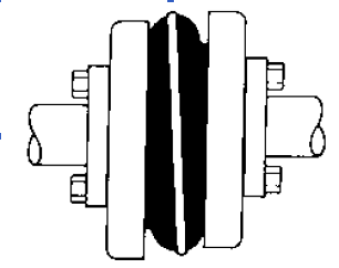 Design Torque of the application by multiplying the Nominal Torque calculated in Step 1 through the Application Services Element established in Stage two.
Design Torque = Nominal Torque x Application Service Element
Stage four: Utilizing the Sleeve Effectiveness Data Chart two choose the sleeve materials which most effective corresponds to your application.
Phase 5: Making use of the S-Flex Nominal Rated Torque Chart 3 locate the proper sleeve material column for the sleeve selected in Phase 4.
Phase 6: Scan down this column towards the very first entry exactly where the Torque Worth within the column is better than or equal for the Design and style Torque calculated in Step three.
Refer for the optimum RPM worth with the coupling size to make certain that the application prerequisites are met. In the event the greatest RPM value is much less than the application requirement, S-Flex couplings are not recommended to the application.
Note:
If Nominal Torque is much less than 1/4 in the coupling’s nominalrated torque, misalignment capacities are decreased by 1/2. After torque worth is located, refer for the corresponding coupling dimension in the to start with column of the S-Flex Nominal Rated Torque Data Chart three .
Phase seven: Compare the application driver/driven shaft sizes towards the maximum bore dimension available within the coupling picked. If coupling max bore isn’t large ample for your shaft diameter, pick the subsequent biggest coupling that could accommodate the driver/driven shaft diameters.
Stage 8: Making use of the Item Selection tables, discover the suitable Keyway and Bore dimension essential and find the amount.